Research Article 
![]() Creative Commons, CC-BY
Creative Commons, CC-BY
Finite Element Analysis of Total Knee Arthroplasty
*Corresponding author: Mohammad Noori, Department of Mechanical Engineering, California Polytechnic State University, San Luis Obispo, United States.
Received: August 12, 2021; Published: August 25, 2021
DOI: 10.34297/AJBSR.2021.14.001942
Abstract
Total knee arthroplasty (TKA) has become one of the most common operations in all of medicine, with an average of 966,000 performed annually in the United States. Since its introduction in 1968, TKA surgical techniques and implant designs have improved to increase prosthesis longevity. However, aseptic loosening of TKA components continues to be the most common reason for revision surgery. Ideal implant characteristics, which minimize stress shielding have yet to be determined. The purpose of this study was to investigate how implant design parameters including fixation technique, tibial stem geometry, cement stiffness, and implant-bone frictional interface affect stress shielding within the tibia, and to determine the optimal combination that minimizes this effect. A CT scan of a tibia was used to simulate multiple tibial stem configurations for finite element analysis in ABAQUS. Stress shielding was calculated by using the average minimum principal stress at interval cuts along the length of the tibia. We found that short, fully-cemented stems, high-stiffness hybrid cemented stems, low-stiffness for fully-cemented stems, and a sliding friction interface to be ideal.
Keywords: Finite Element Analysis; Implant Design; Stress Shielding; Total Knee Arthroplasty
Introduction
Total Knee Arthroplasty (TKA), first introduced in 1968, has become one of the most prevalent surgeries in all of medicine. An estimated 966,000 TKAs were performed in the United Sates in 2017, with a projected significant continued increase [1]. The American Academy of Orthopedic Surgeons (AAOS) predicts a 189 percent growth in TKAs by 2030 and 382 percent by 2060, to 1.28 million and 2.60 million procedures annually, respectively [2]. The most common reason for TKA is knee pain due to end stage osteoarthritis causing degenerative destruction of articular cartilage that functions to protect and lubricate the joint surface. During a TKA, the damaged cartilage and bony end surfaces of the distal femur and proximal tibia are resected. Appropriately sized metal implants with a polyethylene spacer are then placed to recreate the joint surface [3].
TKA survivorship is reported to be > 90% at 10 to 15-years. However, aseptic loosening remains the most common cause for re vision TKA (RTKA), accounting for an estimated 31% of revisions, followed by infection (27.4%), instability (7.4%), and periprosthetic fractures (4.7%) [4,5]. Aseptic loosening is theorized to occur due to excess wear particle formation causing an inflammatory response leading to osteolysis and ultimately prosthetic loosening [6]. This wear can be attributed to various patient host factors in addition to surgical and prosthetic elements such as but not limited to fixation technique and implant material [7]. The immense projected increase in annual TKAs will therefore carry an associated significant increase in RTKAs, creating an economic burden for the United States healthcare system [4]. Several studies have investigated how prosthesis design affects the conditions within the tibia which could lead to aseptic loosening [7-9]. One important criteri- on is stress shielding from the TKA implants due to their relatively higher modulus of elasticity, leading to a decrease in bone loading and resultant bone resorption. We sought to investigate how different designs of tibial TKA components impact stress shielding and most closely replicate the conditions of a native, normal tibia.
Existing Studies
Prior studies have explored the effects of TKA implants on surrounding bone through modeling. This work has provided insight on both the inadequacies and advantages of each analytical approach. Completo, et al. [7]. utilized a finite element model to confirm the prevalence of stress shielding in longer tibial stems. However, they limited their work to a hybrid fixation, in which cement is applied beneath the tibial baseplate, and a 40/60 axial loading distribution between each tibial condyle [7]. They showed that short stems exhibit minimal stress shielding, while long stems induce stress shielding up to half of the stem length. They also demonstrated that at the stem tip, stress concentrations can reach up to 4.5 times higher in short stems, and 7 times higher in long stems compared to the intact tibia. However, they identified that an ideal stem length is guided both by mechanical characteristics in addition to patient factors such as bone quality and quantity Chong, et al. [7]. studied the long-term bone resorption effects of fully cemented, hybrid cemented, and cement less fixation techniques with three levels of integration between the bone and stem [8]. The levels of integration were intended to represent the extremes of clinical circumstances and were simulated using different frictional conditions. They found greater bone density at the stem tip in the hybrid model compared to the fully cemented model, and that bone resorption in lower integration (lower friction) occurred at almost half the rate of those in higher integration (higher friction). Full cementation may provide better initial stability but can have detrimental long-term effects on bone quality. They concluded that a hybrid cement technique, resulting in partial ingrowth, may allow for greater preservation of bone stock. Eidel, et al. [9]. Examined the result of modifying bone-stem interface conditions [9]. By varying the fixation technique and the friction conditions in the bone-stem interface, they confirmed the presence of stress shielding in models with “stiffer” friction conditions. The “stiffness” of each model was ranked in a decreasing order: full cement, surface cement with osseointegration, and surface cement with a 0.2 and 0.0 coefficient of friction. The results showed that stress shielding can be greatly reduced despite a large mismatch in implant and bone stiffness if the interface is compliant in sliding friction conditions. Another study by Completo, et al. [7]. Investigates the load sharing and stability of various fixation techniques. Similar loading conditions were used to account for a 60 and 40 percent distribution of axial body force between the medial and lateral sides of the tibial baseplate, respectively. The model also included an anterior-posterior load, an internal- external moment, and a patellar-ligament force. The study confirmed that short, cement stems produce tray stability equivalent to that of long press-fit stems [10].
Materials and Methods
The primary objective of this study was to investigate how fixation
technique, tibial stem geometry, cement stiffness, and interface
conditions affect stress shielding within the tibia, and to find
an optimal combination of designs that produce the least amount of
stress shielding. This was pursued as outlined below:
i. To accurately compare the designs, finite element analysis was
used to model both the pre- and post-TKA tibia and compare
the stresses. A CT scan three-dimensional model of a tibia was
used as the baseline and further modified in order to accommodate
TKA designs. The tibia, tibial stem, and tibial tray were
considered in the model as the remaining femoral component
and spacer in the TKA are represented as a load on the tibia.
ii. The tibia was modeled as a single material and loading on the
tibial plate was represented as axial loading at the medial and
lateral regions in order to accurately simulate the forces within
the knee joint. Varying stem lengths (short, medium long),
fixation techniques (fully cementation, hybrid cementation),
cement stiffnesses, and interface conditions were used to generate
multiple models.
iii. After the feasibility of models for the pre-TKA tibia and post-
TKA tibias were verified, the stresses at specific locations
along the tibia were compared in order to compute the magnitude
of stress shielding present in each design. This revealed
the optimal combination of designs for a TKA.
In order to build a TKA model, a provided three-dimensional
reformatting of a CT scan of the tibia was prepared in SolidWorks
and MeshLab. The prostheses were then modeled in SolidWorks
and the assemblies were generated for each configuration. A total
of 15 assemblies were created for the different combinations of
stem geometry, fixation technique, cement material, and interface
condition. These assemblies were imported into Abaqus for analysis
and evaluation of results.
Model Preparation
The “Standardized Tibia” – a 3D model derived from a CT scan of a synthetic human tibia – was selected for this study. The model was provided by Pacific Research Labs in a public domain as a STL file. MeshLab was used to repair and reduce the mesh from 55,000 to 33,750 faces. The model was then imported into SolidWorks to create a 10-millimeter resection from the proximal tibia, which was determine based on the existing dimensions of the tibial condyles, and a mid-diaphyseal cut for a constraint, as shown in Figure 1 [11]. Material was then removed at the resectioned surface to accommodate different implant configurations.

Figure 1: 1: Tibia model before (left) and after (right) preparation.
Tibial stem and cement techniques were modeled in Solid- Works and combined to form several TKA configurations, as shown in Table 1. The hybrid cementation fixates the resected face of the tibia and bottom surface of the baseplate, while the full cementation additionally includes cementation of the stem. A 60-millimeter stem has versatile applications and therefore more configurations were used with that length [12]. Implant dimensions were selected based on the Stryker Triathlon Total Knee System [13] with an added 2-millimeter thickness for the cement mantle. The models were imported into Abaqus for FEA.

Table 1: Combination of design parameters for different TKA configurations (HY - Hybrid, F - Full, PF – Press fit, L – low, M – medium, H – high, B – bonded).
Finite Element Model
The assigned material properties shown in Table 2 were assumed to be homogeneous, isotropic, and linearly elastic. The young’s modulus of the bone and cement were selected based on reported values in existing studies. The different values for cement stiffness were selected to encompass low to high stiffnesses.

Table 2: Material properties of components in TKA.
To simulate contact between the different components of the TKA, a general surface-to-surface contact formulation was used. As highlighted in Table 1, the cement-bone interface was assigned bonded and coefficients of friction μ = 0.3, 0.5, while the bone-implant interface was assigned bonded and coefficients of friction μ = 0, 0.3.
In order to simulate forces on the joint, a non-uniform loading was assigned to the medial and lateral condyles. A 60% medial and 40% lateral distribution of 1588 N and 1059 N was assigned respectively, to account for a 90-kilogram human and dynamic loading factor of 3. The loads did not account for the forces from ligaments, muscles, and tendons. The bottom face at the cut distal region was assigned a fixed constraint.
The assembly was meshed in Abaqus using 10-node tetrahedral elements (C3D10) and mesh convergence was determined at a seed size of 1.5 mm. An Abaqus based mesh verification [14] ensured that the percentage of element distortion for all models did not exceed 0.22%. In post-processing, the cross section of the tibia was divided into four regions: medial, lateral, posterior, and anterior. The stresses were analyzed for each region at increments of 10 mm for areas at which the stem is present in order to more accurately capture the stress shielding along the length of the tibia.

Figure 2: Assembly loading, boundary condition, and mesh.
Results
Stress Shielding and Intact Tibial Stresses
In order to quantify stress shielding, the stresses within the intact tibia had to first be obtained. Similar to the approach taken in the studies of Completo, et. al [5] and Bautista [15], the minimum principal stress was used to compute stress shielding. According to Completo, et. al. stress shielding is defined by the following equation,
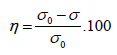
where η is the stress shielding, σ_o is the intact tibial stress, and σ is the post-TKA stress. Stress shielding is represented as a percentage, where a negative value indicates that the post-TKA tibial stresses have decreased relative to the intact tibia and stress shielding is present. (Figure 3) locates where the stress in the z-direction is zero – otherwise known as the neutral plane – for the intact tibia. The neutral plane provides an indication of the bending behavior of the tibia and its location is determined by geometry and loading. As seen on the plot, the tibia is predominately in a state of compression. The posterior and medial tibia is in compression while a small region of the anterior side is in tension.

Figure 3: Neutral plane (left) and average minimum principal stress along tibia.
Stem Length and Fixation Technique
Since there is a correlation between the stem length and fixation technique, those parameters were varied while the cement stiffness and interface condition were kept constant. Stress shielding was present along the stem in all models. As shown in Figure 4, the stress shielding beneath the tibial baseplate was found to be high in all models and decreased overall approaching the stem tip. In the 60- and 100-millimeter models, there was a local decrease in stress shielding around the 10 to 20-millimeter range before subsequently increasing then decreasing back to physiological levels near the stem tip, where the stress shielding was close to 0%.

Figure 4: Stress shielding along tibia in the medial and lateral regions for varied stem lengths and fixation techniques.
Past the stem tip, the stresses were consistently maintained near physiological level in all models. Long stems demonstrated significantly greater overall stress shielding compared to short stems, independent of the fixation method. The press-fit configuration experienced the least amount of stress shielding beneath the baseplate compared to hybrid and full cement configurations. The fully cemented models however, showed the lowest stress concentrations near the stem tip. Moreover, all of the stems contained much larger compressive stresses compared to the surrounding bone, as shown in the contour plots in (Figure 5 & 6) locates the neutral planes of configurations with varying stem lengths and fixation techniques.

Figure 5: Stress contour plots in the frontal plane for varied stem lengths and fixation techniques.

Figure 6: Left: Neutral plane of the intact tibia (red), 25mm (yellow), 60mm (blue), and 100mm (purple) stemmed tibias. Right: Neutral plane of the intact tibia (red), 60mm hybrid cement (blue) and 60mm full cement (yellow) tibias
Cement Stiffness
Overall, the cement with the lowest stiffness induced the greatest amount of stress shielding in the hybrid cement configuration and the least amount in the full cement configuration. As shown in Figure 7, the stress shielding beneath the baseplate increased slightly with a decrease in cement stiffness for both configurations. This was the only noticeable difference within the hybrid cement models. Moving distally along the stem, the stress shielding in the hybrid cement models quickly converged and remained at the same level throughout the tibia. However, the full cement models had relatively larger differences in stress shielding for varying cement stiffnesses, specifically in the 20 to 50-millimeter region. As shown in Figure 8, the stresses at the stem tip were much higher in the hybrid cement configuration than in in the full cement configuration. Additionally, the least stiff cement induced the lowest stresses at the stem tip among the full cement models.

Figure 7: Stress shielding along tibia in the medial and lateral regions for varied cement stiffnesses.
Interface Conditions
The bonded interface consistently exhibited more stress shielding throughout the tibia, whereas the sliding friction condition (unbonded) exhibited lower but nearly identical levels of stress shielding. As shown in (Figures 9 & 10), there was an up to 20% difference in stress shielding between the bonded and sliding interface conditions in the 20 to 50-millmeter region. The stress shielding at the stem tip was higher for the bonded cases, whereas the bending stresses within the stem were lower for the sliding friction cases.

Figure 8: Stress contour plots of tibia viewed in frontal plane for increasing cement stiffness (left to right) for hybrid (left 3) and full cement (right 3) models.

Figure 9: Stress shielding along tibia in the medial and lateral regions for varied stem-cement interface conditions.

Figure 10: Stress shielding along tibia in the medial and lateral regions for varied stem-bone interface conditions.

Figure 11: Stress contour plots of tibia viewed in frontal plane for varied stem-cement interfaces (1-3) and stem-bone interfaces (4-6). 1-3 (left to right): bonded, μ =0, μ =0.3. 4-6 (left to right): bonded, μ =0.3, μ =0.5.
Discussion
Stem Length and Fixation Technique
The stress shielding trends observed in the medial and lateral regions for all models are mostly consistent with expectations, according FEA studies conducted by Bautista [15] and Completo, et al. [7]. All models demonstrated a large amount of stress shielding beneath the baseplate and distally along the tibia. However, a study conducted by Completo et, al. [7] observed stress shielding to be present only up to half of the length of the stem, which was not consistent with our results. Stress shielding was found to be present along the entire stem, which alters the load transfer mechanism and deflection. The effects on the load transfer mechanism play a much larger role in influencing the stresses than the deflection. However, it is still important to note that the implantation of a stiff stem changes the deflection in the post-TKA tibia compared to an intact tibia.
In the plot of the neutral plane, the region “behind” the plane, or in the posterior direction, is in compression while the anterior side is in tension. The figure shows that the neutral plane translates and rotates in the direction of the origin with the implantation of the stem. The longer the stem, the more the neutral plane translates and rotates towards the medial region, inducing more tension in the anterior and lateral regions. Contrastingly, the neutral plane only intersects a portion of the lateral region. This explains why the stress shielding in the lateral region is noticeably greater than that in the medial region, especially with longer stems. It is important to note that the shift in neutral axis occurs only along and slightly past the length of the stem. Further distally in the tibia, the neutral planes realign with that of the intact tibia, which partially explains why the stress shielding approaches zero beyond the stem. The behavior of the tibia is comparable to that of a composite beam but more complex due to the asymmetry of the tibia and the non-uniform loading condition.
The effects on the load transfer mechanism are most notable beneath the baseplate and at the stem tip. The region beneath the tibial baseplate is where some of the highest levels of stress shielding occur. As theorized by Eidel et, al. [9], the forces applied to the tibia can be decomposed between the baseplate and the stem. Due to the bond between the stem and the bone, the stem will transmit a majority of the total load applied via shear stresses and axial loads to the bone. Consequently, the tibial plate will see a reduction in force transmission and thus induce stress shielding beneath the plate. Despite this, the 60- and 100-millimeter stems still demonstrated a localized decrease in stress shielding in the 10 to 20-millimeter range due to the compressive loads induced by the tapering region of the stem. The hybrid cemented models induced the greatest amount of stress shielding beneath the tibial plate, followed by the full cement and press-fit models. This can be attributed to the thin layer of cement that is applied beneath the plate in both the hybrid and full cement models. Due to its relatively lower modulus, the cement is less effective in transmitting load to the bone compared to a Titanium-bone interface. This same reasoning along with the fact that cement helps distribute stresses explains why the full-cemented stems see a reduction in stress concentrations at the stem tip.
While Completo, et al. [7] determined stress concentrations at the stem tip of up to 800% of the intact tibia stresses, our results were much lower. The apparent lack of stress concentration at the stem tips are due to the fact that the stresses are averaged across the entire region – not just the interface – which results in an overall lower average stress. When looking at the stress contour plots, stress concentrations are in fact present at the stem tips of every model. The 100-millimeter stems induce large stress concentrations, whereas the 25-millimeter stems do not. According to Robalo [16], localized increase of stresses at the stem tip are attributed to the fulcrum effect. This occurs when the condylar forces generate a bending moment along the stem and “pushes” the stem tip into the bone. The longer the stem, the greater the moment, and thus a greater force seen at the tip. This bending moment can be visualized on the contour plots of the stems.
Cement Stiffness
Changes in cement stiffness also appear to affect the load transfer mechanism and the deflection. Noticeable effects on the stress shielding are seen below the baseplate and at the stem tip. As previously mentioned, this is due to the effect that the modulus has on the ability to transfer load, resulting in lower stress in the low stiffness cement and vice versa. The contour plots in figure 44 show a considerable reduction in stress shielding at the stem tips from the highest to lowest cement stiffness. Beneath the baseplate, stress shielding was more sensitive in the hybrid cement than the full cement configuration. At a maximum, an increase of the cement modulus by 200% yields a reduction in stress shielding beneath the baseplate by about 5% in the hybrid cement model and 3% in the full cement model. This relatively small effect can be attributed to the fact that the modulus of the cement is magnitudes lower than those of its surrounding materials.
The lower stress shielding – specifically in the 20 to 50-millimeter region – of the full cement models can be attributed to the behavior of the bending due to changes in cement stiffness. The full cement model introduces a layer of cement at the region where the bone would be present in the hybrid cement. As shown in Figure 4 & 5, which compares the neutral planes of the hybrid and full cement configuration with that of the intact tibia, replacement of a high modulus bone with a relatively low modulus cement allows the tibia to undergo more deflection and shifts the neutral plane closer that of the intact tibia (in the 20 to 50-millimeter region), increasing the compressive loads throughout. At a maximum, stress shielding in the full cement models see a difference of about 20% between the lowest and highest stiffness cement in the lateral region. Darwish, et al. [17] conducted one of the only studies that investigates the effects of cement stiffness on TKA stresses. Using a hybrid model, Darwish et. al concluded that increasing the stiffness by a maximum of 50% from fairly high levels of 2500 to 3750 MPa would yield optimal stresses in the TKA. Any stiffness beyond that margin would produce undesirable results. The only criteria used to draw this conclusion were the Von-Mises stresses with no reference to the physiological stresses. In contrast to Darwish, et al. [17]. the results found in this study recommend increasing the stiffness of cement in the hybrid cement configurations while decreasing the cement stiffness in full cement configurations. However, further research should be conducted on the effect of reducing stress shielding below the tibial plate for full cemented models due to the stress shielding trade-off between the region beneath the baseplate and the region along the stem and stem tip.
Interface Conditions
With changes in the interface condition, the load transfer mechanism and bending of the tibia are affected. The load transfer mechanism is influenced by the interface’s ability to sustain shear stresses. The higher the coefficient of friction, the more shear stresses develop at the interface. During loading, the condylar forces are primarily transmitted via shear stresses axially at the distal region, thus reducing the stress and increasing the stress shielding in the proximal region. This explains why the bonded interfaces consistently exhibit higher stress shielding and greater stresses at the stem tip. With a sliding friction interface, there is more force transmission through the baseplate, which reduces stress shielding in the proximal regions along the stem. The tibial bending is also influenced by the presence of shear stresses at the interface. Sliding friction conditions allow movement between the contacting surfaces whereas the bonded condition does not. By allowing relative displacement, the bone is able to undergo a deflection closer to that of the intact tibia. The neutral plane of the tibia with sliding friction conditions would shift closer to that of the intact tibia and induce more compressive stresses throughout, reducing the overall amount of stress shielding.
These results partially agree with finite element studies conducted by Eidel, et al. [9] and Chong, et al. [8], which investigated the effects of interface conditions on stress shielding. It is without question that sliding frictional interfaces are preferred when it comes to reducing stress shielding in the tibia. However, these results show that stress shielding cannot be avoided even with sliding friction interface conditions, contrary to the claims by Eidel, et al. [9]. As long as there is implant material within the tibia with largely mismatched stiffnesses, stress shielding will always be present. When considering that the purpose of cement is to provide initial fixation stability in full cement models, it appears difficult to achieve with sliding frictional surfaces. Additionally, the choice of fixation is often governed by the conditions of the tibia. Thus, sliding frictional interfaces can be beneficial for both models in terms of reducing stress shielding, but more studies should be conducted on the trade-off between interface conditions and implant longevity for full cement fixation.
Conclusion
Based on the results of this study, an ideal TKA configuration that yields the least stress shielding would include a short stem with either a hybrid cement with high stiffness cement, or a full cement with a low stiffness cement. The addition of sliding friction conditions demonstrates immediate reduced stress shielding but long-term sustainability is unknown. While this study provided useful insight on the effects of modifying TKA parameters on tibial stress shielding, future research should include more accurately simulating the conditions within the tibia. This study assumed a linear, isotropic, homogeneous material for the bone with a simplified loading condition. In reality, the bone is composed of different material properties and the loading is additionally composed of forces from muscles, ligaments, and tendons. Tibial geometry can differ from patient to patient, which could alter stress distributions. In this study, we used a synthetic model of a tibia, but cadaveric tibias can also be considered for future studies. Also, the material properties of the tibia used in this model correspond to a specific bone condition. In realty, there is a wide range of patients at different ages with differing tibial bone quality, and so the tibia may have varying material properties. Additionally, when taking Wolff’s law into account, the material of the bone surrounding the implant may become stiffer or weaker over time. This adaptive property of bone should also be included for more accurate results. Considering these details may yield similar overall trends since the average values of stress were used to compute stress shielding in this study. However, this would guarantee a more accurate modeling of the tibia which would greatly benefit in assessing the detailed locations at which the stress shielding occurs.
Additional studies should also consider stress shielding for different implant designs. Even though stem length is the primary factor correlated to stress shielding, this study has shown how stress distributions along the stem may be unique to each design. This study selected one of many implants. Specific comparisons of stress distributions should be compared for various implants to determine favorable design features. Lastly, future studies should also focus on the mitigation of stress shielding with cement. Existing literature has claimed one fixation technique or a specific cement stiffness value to be ideal, when in fact that is not necessarily the case. This study has proven hybrid cements to work well with high stiffness cements and full cements to work well with low stiffness cements. Further studies should be conducted on modifying cements to reduce stress shielding. Perhaps using cements with different stiffnesses at select regions of the implant could prove beneficial.
References
- (2018) Total Knee Replacement Statistics 2017: Younger Patients Driving Growth IData Research.
- (2018) Projected Volume of Primary and Revision Total Joint Replacement in the U.S. 2030 to 2060 American Academy of Orthopaedic Surgeons.
- (2020) Total Knee Replacement OrthoInfo - AAOS OrthoInfo.
- Ronald E Delanois, Jaydev B Mistry, Chukwuweike U Gwam, Nequesha S Mohamed, Ujval S Choksi, et al. (2017) Current Epidemiology of Revision Total Knee Arthroplasty in the United States. J Arthroplasty 32(9): 2663-2668.
- William C Schroer, Keith R Berend, Adolph V Lombardi, C Lowry Barnes, Michael P Bolognesi, et al (2013). Why Are Total Knees Failing Today? Etiology of Total Knee Revision in 2010 and 2011.J Arthroplasty, 28(8): 116-119.
- Yunpeng Jiang , Tanghong Jia, Paul H Wooley, Shang You Yang (2013) Current research in the pathogenesis of aseptic implant loosening associated with particulate wear debris. Acta Orthop Belg 79(1):1-9.
- Completo A, P. Talaia, F Fonseca, JA Simões (2009) Relationship of Design Features of Stemmed Tibial Knee Prosthesis with Stress Shielding and End-of-Stem Pain. Materials & Design 30(4): 1391-1397.
- Desmond Y R Chong, Ulrich N Hansen, Rene van der Venne, Nico Verdonschot, Andrew A Amis (2011) The Influence of Tibial Component Fixation Techniques on Resorption of Supporting Bone Stock after Total Knee Replacement. J Biomech 44(5): 948-954.
- Eidel B, A Gote, C P Fritzen, A Ohrndorf, H J Christ (2020) Tibial Implant Fixation in TKA Worth a Revision?—How to Avoid Stress-Shielding Even for Stiff Metallic Implants. Computer Methods in Biomechanics and Biomedical Engineering 24(3):1-13.
- A Completo, J A Simões, F Fonseca, M Oliveira (2008) The Influence of Different Tibial Stem Designs in Load Sharing and Stability at the Cement-Bone Interface in Revision TKA. Knee 15(3): 227-232.
- Christoph Schnurr, György Csécsei, Jochen Nessler, Peer Eysel, Dietmar Pierre König (2010) How much tibial resection is required in total knee arthroplasty? Int Orthop 35(7): 989-994.
- Se Gu Kang, Cheol Hee Park, Sang Jun Song (2018) Stem Fixation in Revision Total Knee Arthroplasty: Indications, Stem Dimensions, and Fixation Methods. Knee Surg Relat Res 30(3): 187-192.
- (2017) Triathlon TS Knee System Product Catalog. Stryker.
- (2009) 17.6.1 Verifying Your Mesh. ABAQUS/CAE User's Manual (v6.6), Simulia, classes.engineering.wustl.edu.
- Bautista, Aaron Isidro, Mohammad Noori (2015) A Finite Element Analysis of Tibial Stem Geometry for Total Knee Replacements. California Polytechnic State University, San Luis Obispo.
- Robalo, Tiago José Fonseca (2011) Analysis of Bone Remodeling in the Tibia after Total Knee Prosthesis. Universidade Tecnica de Lisboa.
- Darwish S m, A Al Samhan (2008) The Effect of Cement Stiffness and Tibia Tray Material on the Stresses Developed in Artificial Knee. International J Adhesion Adhesives 28(3): 120-125.


 We use cookies to ensure you get the best experience on our website.