Review Article 
![]() Creative Commons, CC-BY
Creative Commons, CC-BY
Numerical Simulation and Theoretical Analysis of Reasonable Position of Stop-Mining Line in Deep Mining Face with Large Mining Height
*Corresponding author: Guo Jingzhong, School of Safety Engineering, North China Institute of Science and Technology, China.
Received: September 01, 2023; Published: September 06, 2023
DOI: 10.34297/AJBSR.2023.20.002669
Abstract
In order to study the reasonable position of stop-mining line in deep and large mining height working face, this paper takes 1405 working face of Daliu Mine as the research object, adopts FLAC3D numerical simulation, combined with theoretical calculation and other methods to analyze the pressure distribution and ore pressure characteristics of the ore body. The results show that:
1) the position of 3~10m of the leading working face is the range of intense influence, and the peak value is located 5 m in front of the leading working face, and the peak value is 73.6MPa; When it is 15m away from the working face, the abutment pressure does not fluctuate in a wide range and is stable at 16~20MPa. In the range of 30m in front of the working face, the influence of advanced abutment pressure is small, close to the original rock pressure.
2) When the distance between the working face and the west wing roadway is less than 30m, the ore pressure caused by the superposition of the influence of advance mining and the influence of pressure and deformation after roadway excavation is intense; When the distance between the working face and the roadway is more than 30m, the superposition effect of the two decreases gradually with the greater the distance.
3) The theory of mining influence range of the working face at the stop-mining line in the west wing return roadway should be 30~35m; Based on the calculation of the coefficient of loose circle and pillar protection, it is concluded that the reasonable position of stop-mining line is 44~60 m away from the west wing rewind alley.
Keywords: Deep buried large mining height, Stopping line, Advance abutment pressure, Pillar size
Introduction
With the gradual development of mining towards deep areas, the depth and quantity of tunnels reaching the mining horizon of the ore body have significantly increased; At the same time, the mining cost of deep ore bodies is generally higher than that of shallow layers, and it is necessary to further improve the extraction rate of deep mines to make up for expenses; The two have resulted in a reduction in the spacing between tunnels within a fixed space and the spacing between tunnels and ore layers [1,2]. This type of phenomenon has a significant impact on the stability of deep ore bodies. Therefore, it is necessary to clarify the reasonable position of the stopping line in the working face to ensure the normal operation of the roadway. However, insufficient retention of pillars on the stopping line will affect the stability of the mining roadway, and excessive retention will also reduce the recovery rate of the ore body [3,4]. How to determine the reasonable stop mining line position is an urgent problem to be solved at present. When the working face is mined to a certain horizontal distance from the main roadway, the surrounding rock of the roadway will be affected by mining. As the working face continues to advance, the impact of advanced mining and the stress concentration effect of excavation in the main roadway are superimposed, seriously affecting the stability of the main roadway. Therefore, the reasonable selection of the stop mining line position for the working face should consider the range of the excavation influence area of the main roadway, the range of the mining advance influence area of the working face, and the safety distance between the superimposed influences of the two areas [5,6]. Numerous scholars have conducted extensive research on the rational selection of mining stop line positions [7]. Used acoustic emission instruments to monitor the deformation process of the surrounding rock of the model roadway and obtain the overall deformation amount under the similar simulation test of the mining progress of the working face. They summarized the development and evolution characteristics of the surrounding rock fractures and clarified the influencing factors for the reasonable location selection of the stop mining line [8,9]. Studied high stress working faces under complex conditions and used numerical simulation to analyze the distribution of cracks around the stopping line. Based on on-site measured data, the influence range of advanced support pressure on the working face was obtained, and the position of the stopping line was jointly determined [10]. Established a composite beam mechanical model, clarified the location of the key layer, calculated the load distribution on the upper part of the key layer of the overlying rock in the working face, analyzed the stress distribution characteristics of the ore body under the fracture of the key layer, proposed the evaluation criteria for tunnel stability, and provided theoretical support for the reasonable layout of the stopping line in the working face. By using theoretical analysis, numerical simulation, similarity simulation, and on-site monitoring methods, the width of the pillar is determined from multiple perspectives around the stress and deformation characteristics of the surrounding rock, and the reasonable location for stopping mining at the working face is determined [11-16]. The setting of the stop mining line mainly considers the influence range of mining advance, the influence range of excavation cracks in the front roadway, and the safety factor between the two. This article is based on the geological conditions of deeply buried coal seam working faces and uses FLAC3D numerical simulation method to study the superposition effect of the advanced influence range of the working face and the stress influence range after excavation of the main roadway and provide the position of the stop mining line. Based on theoretical analysis, optimize the position of the stope line and clarify the reasonable interval for pillar placement.
Project Overview
The strike length of the high mining height working face is 1850meters, and the dip width is 231meters; The average thickness of the ore body layer is 5.5meters, with an inclination angle of 2-17°. The south side of the working face is divided into three main alleys on the west wing, as shown in (Figure 1).

Figure 1: Location of three main alleys.
Analysis of Advance Abutment Pressure Measuring
To determine the distribution pattern of abutment pressure in the direction of the working face, a measuring station is arranged every 10m in front of the working face, as shown in Figure 2. Based on the observed data, the leading vertical stress variation curve is analyzed, as shown in (Figures 3-7).
Based on the comprehensive analysis of Figures 3-7, it can be seen that:
1) When the distance from the working face is beyond 15meters, there is no significant fluctuation in the support pressure, which is basically stable at 16-20MPa; When the mining face reaches 15meters from the 1# measuring station, as the mining face continues, the support pressure gradually increases, with the maximum pressure being 73.6MPa.
2) The peak stress appears at a position of 5meters in front of the work face, with a severe influence range of 3 to 10meters in front of the work face. Within a range of 30 meters in front of the work face, it is less affected by advanced support stress.

Figure 2: Layout of advance abutment pressure measuring station.

Figure 3: Advance abutment pressure of 1 # measuring station.

Figure 4: Advance abutment pressure of 2 # measuring station.

Figure 5: Advance abutment pressure of 3 # measuring station.

Figure 6: Advance abutment pressure of 4 # measuring station.

Figure 7: Advance abutment pressure of 5 # measuring station.
Analysis of Reasonable Position of Stopping Line in Working Face
Modeling
FLAC3D numerical simulation software is a numerical analysis method based on the three-dimensional explicit finite difference method. It has a rich constitutive model library, powerful analysis functions, and discontinuous feature analysis capabilities, which can effectively simulate the three-dimensional structural stress characteristics and plastic flow analysis of soil, rock, and other materials. This article uses the molar Coulomb model and provides the following explanation:
(1) Incremental elasticity law
The three-dimensional stress environment of rock mass, with stresses of σ1 ,σ 2 ,σ 3 , respectively, where the corresponding principal strain increment ( Δe1 ,Δe2 ,Δe3 ), which can be decomposed into:

Formula, j takes 1, 2, and 3; e represents the elastic zone, and p represents the plastic zone.
The increment of each principal stress is shown in formula (3):
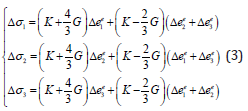
Formula, K represents the bulk modulus, and G represents the shear modulus. Formula.
Using FLAC3D numerical calculation software to calculate the model with 400m×300m×42 meters after mining. Apply pressure on the upper boundary of the model to analyze the advanced support pressure of the 1405 working face and establish a numerical calculation model as shown in Figure 8. The size of the model makes it equal to the weight of the overlying rock layer, the bottom boundary is fixed vertically, and the left and right boundaries are fixed horizontally. The mechanical parameters of the rock layer are shown in Table 1.

Figure 8: Initial model.

Table 1: Mechanical parameters of rock strata.
Analysis of Reasonable Location of Stop Mining Line
Simulating the superposition effect of the influence of advanced mining on the working face and stress deformation after excavation on the stability of the surrounding rock of the main roadway under different stopping line positions (20m, 30m, 40m, 50m, 60m, 70m, 80m). The simulation results are shown in Figures 9-15.

Figure 9a: Stress distribution.

Figure 9b: Plastic zone distribution.
Figure 9: Stopping line of 20m away from the return air main roadway for the west wing.

Figure 10a: Stress distribution.

Figure 10b: Plastic zone distribution.
Figure 10: Stopping line of 30m away from the return air main roadway for the west wing.

Figure 11a: Stress distribution.

Figure 11b: Plastic zone distribution.
Figure 11: Stopping line of 40m away from the return air main roadway for the west wing.

Figure 12a: Stress distribution.

Figure 12b: Plastic zone distribution.
Figure 12: Stopping line of 50m away from the return air main roadway for the west wing.

Figure 13a: Stress distribution.

Figure 13b: Plastic zone distribution.
Figure 13: Stopping line of 60m away from the return air main roadway for the west wing.

Figure 14a: Stress distribution.

Figure 14b: Plastic zone distribution.
Figure 14: Stopping line 70m away from the return air main roadway for the west wing.

Figure 15a: Stress distribution.

Figure 15b: Plastic zone distribution.
Figure 15: Stopping line 80m away from the return air main roadway for the west wing.
As shown in Figure 9, when the stop mining line is located 20m away from the west wing return air roadway, both the return air roadway and the main transportation roadway are in a stress increase zone, while the auxiliary transportation roadway is in the original rock stress zone. At this time, the stress around the west wing return air roadway is 45.6MPa, with a stress concentration coefficient of 2.76; the stress around the main transportation roadway is 27.3MPa, with a stress concentration coefficient of 1.65. The combined effects cause the development of the plastic zone, which is only 5.2meters away from the west wing return air roadway. The impact on the return air main roadway and main transportation main roadway is significant, while the impact on the auxiliary transportation main roadway is small.
As shown in Figure 10, when the stop mining line is 30meters away from the west wing return air main roadway, the stress around the return air main roadway is 30.8MPa, with a stress concentration coefficient of 1.98, and the stress around the main transportation main roadway is 16.9MPa, with a stress concentration coefficient of 1.02. The superimposed effects cause the development of plastic zones to be 12.3meters away from the return air main roadway, which has little impact on the return air main roadway and the main transportation main roadway.
As shown in Figure 11, when the stop mining line is 40meters away from the west wing return air roadway, the stress increases in the area around the west wing return air roadway, the stress around the west wing return air roadway is 20.7MPa, and the stress concentration coefficient is 1.25.
As shown in Figure 12, when the stop mining line is 50meters away from the west wing return air roadway, the west wing return air roadway is located in the original rock stress zone. The stress around the west wing return air roadway is 17.1MPa, and the stress concentration coefficient is 1.03. The superimposed influence causes the development of plastic zones to be 22.7meters away from the return air main roadway, with little impact on the return air main roadway and the main transportation main roadway.
As shown in Figure 13, when the stop mining line is 60meters away from the west wing return air main roadway, the three main roadways are in the original rock stress zone, with a maximum stress of 17MPa and a stress concentration coefficient of 1.02.
As shown in Figure 14, when the stop mining line is 70meters away from the west wing return air main roadway, the three main roadways are in the original rock stress zone, with a maximum stress of 16.9MPa and a stress concentration coefficient of 1.02.
As shown in Figure 15, when the stop mining line is 80meters away from the west wing return air main roadway, the three main roadways are in the original rock stress zone, with a maximum stress of 16.7MPa and a stress concentration coefficient of 1.02.
According to the comprehensive simulation results, when the stress range of the advanced support of the working face is 30-40meters, the combined effect of mining and excavation stress on the three west wing main tunnels has almost no effect.
Determination of Reasonable Position of Mining Stop Line in the Working Face
The numerical simulation calculation results show that when the stress range of the advanced support of the working face is 30-35meters, the stress in front of the ore wall is almost close to the original rock stress and is almost unaffected by mining stress. At the same time, in engineering practice, it is also necessary to consider the development range of loose zones in the surrounding rock of the roadway and the production safety factor, in order to comprehensively calculate the reasonable stop mining line position.
Loosening Circle Range
The working face roadway has a trapezoidal cross-section, with an upper net width of 4.3m, a lower net width of 5.0m, a net height of 4.35m, and a cross-sectional area of 20.7m2. For the calculation of loose zones in non-circular tunnels, the circular standardization method is used to determine the influence of tunnel section size and shape. The standardized calculation formula for circular noncircular tunnels is:

Formula, rs is equivalent radius of the tunnel, m; S is cross-sectional area of the roadway; x K is correction coefficient of tunnel cross-section, taken as 1.1.
Combining Formula (1), it can be calculated that rs =3.08 m˳
Calculation of surrounding rock loosening circle, as shown in the formula (2):
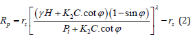
Formula, γ is Average volumetric force of overlying strata, 25 kN/m3; H is Tunnel burial depth, 550 m; Pi is support resistance, 0.2 MPa; R0 is theoretical radius of tunnel, 3.08 m; C is cohesive force of rock mass, 2.5 MPa; ϕ -friction angle, 36°; K2 is correction factor, 1/3~1/2, λ -lateral pressure coefficient, 1.5.
Substituting the above parameters into formula (2) yields, Rp =4.24 m.
Therefore, the distance between the stop mining line and the west wing return air roadway should be the sum of the influence range of the advance support pressure and the range of the loosening zone, which is 35+5m (maximum value rounded); Therefore, the theoretical range of influence of mining on the working face at the stop line of the west wing return air roadway should be 40meters.
Safety Factor for Protecting Mining Pillars
According to the theory of pillar design, pillars, as the main means of controlling the movement and damage of overlying strata, must be able to maintain long-term stability. If the load on the pillar reaches the ultimate strength of the pillar, the bearing capacity of the pillar will be reduced to zero, and the pillar will be destroyed. The commonly used formula for calculating pillar strength and pillar stability in mines suggests that when the safety coefficient of the pillar is 1.1 ≤ k0 ≤1.5, it can be considered that the pillar has long-term stability.
Therefore, the formula for calculating the distance between the stop line position of the fully mechanized mining face and the west wing main roadway is as follows:

When the local layer is stable, k0 is taken as 1.1; When the working face encounters complex geological conditions, k0 is taken as 1.5.
So, according to formula (3), the reasonable position of the stop mining line should be 44-60meters away from the west wing return air roadway. Therefore, from a simulation perspective and combined with the analysis of the engineering geological conditions of the fully mechanized mining working face, it is determined that the position of the stop mining line is 50 meters away from the west wing return air roadway.
Stress Testing of Anchor Rods
Three measuring points are arranged in the west wing return air roadway to record the changes in anchor stress during the progress of the working face. The layout of the measuring stations is shown in Figure 16.
From the analysis of Figures 17-19, it can be seen that the strain of the anchor rod begins to decrease when the working face is advanced to a distance of 65 to 40meters from the west wing return air roadway. It can be inferred that the influence of the working face advancement and the excavation stress of the roadway have an impact on the anchor rod of the west wing return air roadway. In summary, the reasonable position of the stop line in the fully mechanized mining face is shown in Figure 20.

Figure 16: Layout of anchor rod measuring station.

Figure 17: Anchor bolt strain of 1# station.

Figure 18: Anchor bolt strain of 2# station.

Figure 19: Anchor bolt strain of 3# station.

Figure 20: Reasonable location of stopping line.
Conclusion
1) Based on the analysis of measured rock pressure data, the range of severe impact is 3-10meters in front of the work, with a peak value of 73.6MPa located 5 meters in front; when the distance from the working face is beyond 15meters, there is no significant fluctuation in the support pressure, which is basically stable at 16-20MPa; within a range of 30meters in front of the working face, the influence of advanced support stress is relatively small, approaching the original rock stress.
2) Based on numerical simulation analysis, it can be concluded that when the working face is within a range of 30meters from the west wing main roadway, the superimposed effect of advanced mining and the stress deformation effect after excavation of the main roadway will result in severe rock pressure; when the distance between the working face and the main roadway is higher than 30meters, the superposition effect of the two gradually decreases with the increasing distance; when the advance working face is 30-40meters, the impact of mining on the roadway and surrounding ore bodies is within the scope of the project.
3) Based on theoretical analysis and numerical simulation, it can be concluded that the theoretical range of influence of mining on the west wing return air roadway at the stope line should be 30-35 meters. Based on the calculation of the coefficient of loose zone and protective pillar, it is determined that the reasonable position of the stop mining line is 44-60meters away from the west wing return air roadway.
Acknowledgments
None.
Conflict of Interest
None.
References
- Wan Chuanchuan, Zhou Yucheng, Liu Lishhun (2023) Study on Ore-drawing Parameters of Deep Orebody Pillarless Sublevel Caving in Songhu Iron Mine. Nonferrous Metal Engineering 13(01): 99-105.
- Luo Gang (2021) Research on the Stability Control Technology of Surrounding Rock in the Withdrawal Channel of the Fully Mechanized Mining Face Stop Line. Doctoral thesis, China University of Mining and Technology, Xuzhou, China.
- Jing Yanmin (2020) Study on location determination of stop-mining line in Fully Mechanized Coal caving. Energy and Energy Conservation (05): 80-81.
- Liu Jiawei, Huang Mingqing, Tan Wei (2023) Optimization of stope structure parameters based on extended Mathew’s stability graph method. Nonferrous Metals Engineering 13(01): 106-113.
- WEI Bin Study on reasonable position of stop-mining line in Close seam working face. Coal Technology 39(05): 46-49.
- Zhao Meng, Ma Zhifeng, Li Chenghai Study on late Mining Stability of Gudao Working Face under impact risk. Coal Technology 41(04): 1-6.
- Zhou Hui, Qu Chengkun, Huang Jianli (2017) Structure analysis of rational stop-mining line in deep coal seam based on model test. Chinese Journal of Rock Mechanics and Engineering 36 (10): 2373-2382.
- Xiang Xiaoyu, Yang Xuerui, Ma Chengfu (2022) Determination of reasonable location of stop-mining line in weakly consolidated soft rock working face under fault influence. Coal Technology 41(06): 29-33.
- Suo Yonglu, Qi Xiaohu,Liu Jiandu (2014) Determination of reasonable location of stop-mining line in very short distance coal seam. Coal Technology 33(09): 193-195.
- Jing Junjie (2013) Research on determination method of stop-mining line Location based on key layer theory. Coal Technology 32(11): 27-29.
- Wang Gaowei (2021) Analysis of stopping position scheme of Xiabaodang Mine 112201 first Face. Coal Technology 40(04): 5-7.
- Sun Haiying (2019) Research and practice on the support scheme of 6 m inner fault in close stopping line of coal seam Coal Technology 38 (11): 3-6.
- Ma Xinping (2016) Pressure distribution of coal under the influence of stop-mining line based on PASAT-M detection. Coal Science and Technology (03): 43-45.
- MA Xiang (2015) Research and Support Design of stopping pillar in top coal Caving face. Coal Science and Technology (04): 69-71.
- Luo Weirong (2019) Optimization Design of stop-line in Fully Mechanized Mining Face and technology of roof cutting and roadway protection. Jiangxi Coal Science and Technology (03): 160-162.
- Liang Xin (2019) Rational Determination of Stopping Line Location. Shanxi Metallurgy 42(02): 155-157.


 We use cookies to ensure you get the best experience on our website.