Review Article 
 Creative Commons, CC-BY
Enhancement of Bone Canal Drilling Process and Equipments: The Impact of Technology and Knowledge Transfer from Oil Well Drilling Techniques
*Corresponding author: Catalin Teodoriu, Mewbourne School of Petroleum and Geological Engineering, University of Oklahoma, USA.
Received: April 20, 2020; Published: April 29, 2020
DOI: 10.34297/AJBSR.2020.08.001311
Abstract
Bone fracture or bone loss can happen as a result of automobile and motorcycle accidents, falls from a height, sports injuries, aging population and other diseases, for which surgical procedures to support the bone with the help of a metallic rod is applied using a specific procedure called bone drilling. The bone-drilling process necessitates an accurate and efficient surgical drill bit to minimize thermal damage or additional impairment to the bone. The success of this process is dependent upon the eminence of the drilling procedure, drilling equipment and hands -on experience of the specialists performing the operation while minimizing associated injury to the surrounding tissue, or the significant rise of temperature to the neighboring bone and periosteum due to the conversion of friction energy to the thermal energy. The current technology for bone rods implants depends highly on the experience of the specialist performing the operation. There are numerous companies on the market that deliver bone drilling equipment; however, the selection process of a specific tool and the training involved are ultimately the choices of the specialist. Nevertheless, the need in meeting an accurate efficient operation of these in-market drilling bone equipment continues to be a challenge as many pertinent questions remain without solutions.
This paper demonstrates the inconsistency in bone drilling process and equipment alongside with training insufficiency of specialists and highlight the importance of technology and knowledge transfer.
This research provides groundwork in adopting lessons learned from oil well drilling process and frameworks which can be very effective for optimal bone drill procedures can cause both mechanical and thermal damages to both bone and surrounding tissues.
Keywords: Bone fracture; Bone drilling and equipment Specialist; Knowledge transfer; Oil well drilling
Abbreviations: IM: Intramedullary Rod; CT: Computed Tomography; LED: Light-Emitting Diode; PCBN: Polycrystalline Cubic Boron Nitride; ROP: Rate of Penetration
Introduction
Bone is an exceedingly dynamic tissue and the main constituent of the human skeletal system. It is a fossilized connective tissue forming the major portion of the skeleton of most vertebrates. Fracture of bones and related injuries or diseases is as old as their extreme existence. Bone fracture therapy for which surgical procedures called bone drilling is essential and implemented, involves restoring or reinforcing the fractured sections to their preliminary position and immobilizing while undergoing the healing process. As bone repair is termed to be very complex, the literature reveals that approximately 10-15% of all operated fractured bones have a long delay healing and prolonged immobilization [1].
Drilling of bone is a common procedure in clinical surgeries by creating a hole for screw insertion to restore fractured bone parts for immobilization [2,3]. Bone drilling operation is a common operation in traditional and modern surgery practice for medical applications [4]. The drilling of bone is pervasive in many disciplines of surgery including orthopedics, neurosurgery, dentistry, plastics and reconstructive surgery, craniomaxillofacial, among others. This procedure is very delicate and necessitates high accuracy to drill until the required depth is attained. Lughmani et al. [5] mentioned that assessment and control of bone drilling forces are crucial to preclude drill breakthrough, disproportionate heat and mechanical obliteration to the bone as well as surrounding tissues. This entails a delicate control of instruments with the numerous structures nearby bone including the soft tissues, nerves, skin muscle and vascular structures and the cortical bone [6], examined the effect of drill force for several screw and pin fixations. Karmani & Lam [7] studied the type of drill geometry special effects on bone drilling performance by investigating the different type of orthopedic bone drill bits.
As health care is moving from a classified delivery system to one that features greater transparency, partnership, patient involvement and highly secured efficient bone drilling equipment’s. The integration of engineering and computer technology has provided a broad of inventions which have enhanced surgical performance and improve surgical personnel’s precision. There are numerous companies on the market that manufacture bone drilling equipment; however, the selection process of a specific tool and the training involved are ultimately the choices of the specialist. Louredo et al. [8] reported that bone drilling processes are usually carried out by employing electric or pneumatic manual drilling tools. Operating these tools is very simple and similar to the domestic drilling machines/tools used at home to hang a picture. The surgeon can manage the rotation speed of the drill bit while exerting a certain force against the bone to make the hole. However, the drawback of such drilling tools is that there is no way for the surgeon to estimate when the hole is completed, or the desired depth is attained. He mentioned that at the point of breakthrough the drill bit can be shoved further along the drilling axis due to the inertia of the drilling force. While this undesired consequence may not be very vital when drilling through a wall at home, it can be of considerable importance when drilling a bone since the surrounding tissue can be seriously damaged. Currently, the only means to efficiently stop the drilling practice at the desired depth is based upon the surgeon’s experience and intuition. The need in meeting an accurate efficient operation of these in-market drilling bone equipment continues to be a challenge as many pertinent questions still remain without solutions. Thus, any means of assisting the surgeon during the operation can decrease the prospective for error and damages to the bone tissues. Furthermore, the need for appropriate training of orthopedic specialists towards achieving the fastest drilling with minimum damage to the bone and, more important, the bone marrow is a necessity.
To overcome current limitations of on-market drilling tools and improve bone drilling procedure in the operating theater, an effective technology and drilling operational knowledge of oil and gas industry will be discussed here. Tapping into some of these successfully frameworks and methodologies will offer greater precision and heightens safety by preventing damage to bone and surrounding tissues. Some of the lessons learned will also improve bone drilling equipment taking account of bone drilling parameters and enhance the training capabilities of orthopedic specialists by having repeatable successful operations standpoint and also aid the health professionals in the decision-making process before drilling.
Related Work
It has been reported that mechanical performance of bone derives precisely from its structure, which in healthy tissue is able to withstand complex physiological loading patterns and tolerate damage. This implies that understanding of fracture mechanics and cracking initiation is very critical while drilling through bones. In many research studies associated to fracture mechanics, Louredo et al. [8] mentioned that the distortion and fracture mechanisms at each level of bone’s hierarchical structure contribute to its mechanical integrity, most significantly its strength and toughness. Many authors also understudy and investigated the extent of bone fracturing and how its behavioral precedent during the surgical operation [9]. In their findings, the bones behave more as a quasibrittleness material. Figure 1 shows a R-curve behaviour as a function of bone stress intensity and crack extension. The interpretation from the figure illustrates that as the amount of crack growth upsurges, the amount of stress intensity applied also increases. The toughness approximately doubles over crack extensions of the order of millimeters. Bone toughness is relatively low compared to metallic materials, but very brittle materials when compared with ceramic. Mediouni et al. [10] also examined the acetabular fracture complexity by estimating the parameters such as cortical thickness and hardness or density.
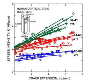
Figure 1: Data from Nalla et al., showing R-curve behavior in human bone samples taken from subjects of different ages.
Bone rod implants are widely used for those situations when the strength of the bone require additional support, and thus a metallic rod (also called Intramedullary Rod - IM) is introduced through the bone marrow canal in order to stabilize it. There are complains of pain or associated symptoms at the location the rods are inserted very often. One critical aspect of proper application of IMs is the need of appropriate training of specialists towards achieving the fastest drilling with minimum damage to the bone and, more important, the bone marrow. Currently, IMs are introduced into the bone canal by hammering (considered to be a dangerous method) or by drilling the bone canal and then inserting the rod. When the drilling method is used, bone marrow recovery is possible, thus difficult.
Presently, there is no standardized universal solution for worldwide training of specialists for drilling through bones activities. Currently, there exist two major technologies; hammering the rods through bone canal (this technique is described by some specialists being outmoded) and the drilling, milling and insertion of rod technology. With more than 50 years of IMs application in the medical industry, the gain experience has shown the importance of proper assessment of the bone canal and geometry as well as reducing the time that require Xray or other real time visualization systems. The use of materials for implants has been diversified concurrently with the advancements of new materials and technologies; latest techniques show the use of rapid prototyping systems for manufacturing on demand the right size of IMs. However, all these advancements depend on the specialist experience and competence to drill (or mill) the bone marrow canal.
The most challenging task is the ability to drill or mill the bone canal while recovering the bone marrow with high efficiency. Technical consultations with various specialists at OU medicine department have revealed that this can be achieved through slow drilling process which on the other hand affects the bone integrity and time under Xray machine. Two of the drilling machines that has been investigated to show a relatively high RPM that could lead to overheating of the bit and hence additionally affecting the bone marrow (Figure 3).
Discussed below are some of the existing and future bone drilling machines/equipment for orthopedic surgery.
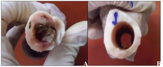
Figure 2: Photographic images of the medullary canal of the femur intact (A) and milled (B) (Bortholon et al., 2013).
Cranial drills
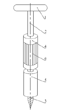
Figure 3: New cranial drill [11]. 1. Handle 2. Rod 3. Drill bit 4. Casing pipe 5. Compass tube 6. Skidproof stripes.
Cranial drill device is designed to drill holes on skull in clinical brain surgery. The new cranial drill developed by Zhan et al. [11] is a characteristic of easy-to-operation, quick drilling, short operation time, and less pain-suffering. Figure 3 shows the portrait of the new cranial drill where, rod 2 is covered by casing pipe 4 with skid proof stripes 6, averting drilling slipping during operation and improve work efficiency. During clinical operation, the compass tube 5 is used to compress the bone drilling position to be located accurately by rotating handle 1. Next, rotate the casing pipe 4 to adjust rod 2 inversely to make rod 2 rotate downward, so that skull will be drilled effectively.
As shown in Figure 4, Jin et al. [12] further invented the handhold automatic cranial drill is characteristic of high safety coefficient because it gives doctors easy control on drilling efforts and could stop automatically after finishing the bone drilling.
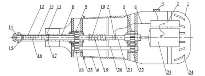
Figure 4: Handhold automatic cranial drill [12]. Hull 2. Current source 3. Switch 4. Connecting line 5. Driving gear 6. Hand department 7. Contact switch 8. Outer drill spindle 9. Outer panel drill shaft gear 10. Inner drill spindle 11. Groove 12. Outer drill bit 13. Spring 14. Drilling teeth 15. Drilling teeth 16. Inner drill bit 17. Convex 18. Drive gear 19. Spring 20. Transmission axis 21. Inner panel drill connecting shaft 22. Driven gear 23. Electric motor 24. Vent 25. Hinge type handrail.
Hao & Fu [13] developed the new directional electric bone drill that could adjust the length of drill bit reasonably. This overcomes the shortcomings of easy-bending and breakage of the bone drill bit and reduces intraoperative trauma by bone drill bit significantly. As illustrates in Figure 5, the power source 9 includes commonly used battery and standby lithium battery. Before using it, the first thing is to choose the commonly used battery or the standby lithium battery by the change-over switch 12, and then open the control switch 11. Before the surgery, rotate the hand wheel of adjusting scale 6 according to the thickness of the drilling skull indicated by CT to make the distance-adjusting push plate 4 cooperate tightly with the drill bit back and forth along the drill bit cover. Turn on LED 3 to improve illumination when necessary. Meanwhile, adjust the length of the drill bit by sliding sleeve 2. In this way, the length of drill bit 1 could be adjusted accurately according to drilling depth. It is an ideal electric cranial drill that controls drilling direction of drill bit 1 as well as accurate drilling by making full use of modern layered scanners (e.g. CT). It is applicable to minimally invasive trepanation, cephalophyma cleaning, ventriculostomy, etc.
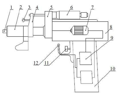
Figure 5: New directional electric bone drill [13]. Drill bit 2. Sliding sleeve 3. LED 4. Push plate 5. Directional board 6. Adjusting scale 7. Micro-motor 8. Hull 9. Power source 10. Hand shank 11. Control switch 12. Change-over switch.
The cranial drill developed by Liu [14] doesn’t need other unit to locate drilling position at the beginning, which brings great convenience to medical staff. As shown in Figure 6, the trigger control switch 12 connects the controller of the cranial drill to power source. Feed motor 9 drives the parts ahead of it move forward. Meanwhile, drilling rod 1 is driven by the main motor 4, which moves forward and rotates concurrently. The guide tube 2 will drill into bones of patient after being stretched out.
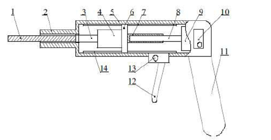
Figure 6: Cranial drill [14]. 1.Drilling rod 2. Guide tube 3. Motor shaft 4. Main motor 5. Shell 6. Slide carriage 7. Internal screw pipe 8. Screw arbor 9. Feed motor 10. Controller 11. Gun type handle 12. Trigger control switch 13. Convert button 14. Lead rail.
Automatic stop bone drills
According to Yang et al. [15], existing drilling systems do need doctors to hold the drill thus resulting in machine poor stability. Additionally, the specified drilled depth depends on doctor’s precise judgement whether the bone has been drilled through. Yong et al. [16] designed an intelligent bone drill and control method, which could provide automatic stop and reverse as presented in Figure 7.
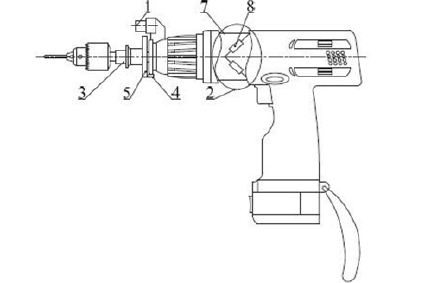
Figure 7: Intelligent bone drill [16]. 1.Ultrasonic transducer 2. Strain torque sensor 3. Drill bit 4. Hall sensor 5. Metal reading dial 7. Annular metal part 8. Strain gages.
The annular metal part 7 is set on the electrical machine of the bone drill, on which there are four strain gages 8 along the + 45° directions. Strain gages 8 use high-temperature ones that could meet needs of high-temperature and high- pressure sterilization. The four strain gages 8 are on the same cross section of the annular metal part 7, forming a strain torque sensor 2 to sense maximum positive and negative strains on axis. If they are used to form a full bridge converter, voltage signal proportional to torque, M could be output. Such connection could get rid of disturbances from axial force and bending force. Torque engendered by the drill bit will be sent to the annular metal part 7 and the intelligent measurement and control module could calculate torque changes on drill bit 3 by measuring the full bridge converter.
The automatic cranial drill invented by Li et al. [17-19] could sense drilling through and stop feeding immediately, protecting brain safety of patients. As illustrated in Figure 8, the rotary power and fore-and-aft shaking forces generated by the motor are the basis of smooth bone drilling. However, fore-and-aft shaking forces are closed when cutting skull. At this moment, the drill could cut skulls as long as the rotary power of motor drives the drill bit 15 to rotate. The drill bit 15 will produce a recoil force during bone drilling to push the motor backward to the force testing unit 12. In this way, drilling-through signal could be detected in first time and the drill will be stopped by computer 21. This protects patients’ safety and minimizes risks. The surgical bone drill with controllable axial force and brazed PCBN super hard drill bit, surgical bone drill with controllable axial force and brazed twist drill bit [20].
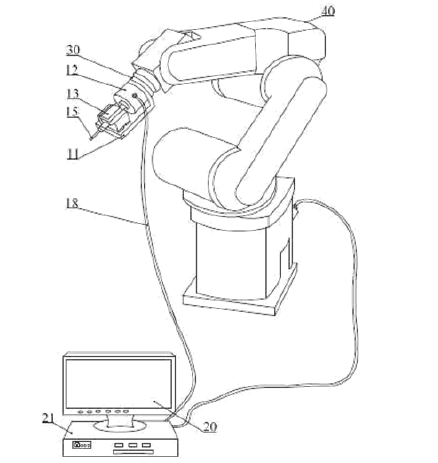
Figure 8: Automatic cranial drill [17-19]. Foundation bed 12. Force testing unit 13. Drive motor fixed seat 15. Drill bit 18. Circuit 20. Core control device Computer 30. Connecting plate 40. Multi shaft type mechanical arm.
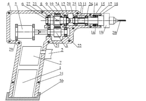
Figure 9: Axial force controllable bone drill [21]. 1. Direct power supplies 2. Control switch 3. Driving gear shaft 4. Shell 5. Continuous current dynamo 6. Driven shaft 7. Intelligent integration control system 8. Flat key 9. Driven gear 10. Axle sleeve 11. Axle sleeve 12. Jam nut 3. Transmission shaft 14. Resistance strain gage 15. Elastic cell 16. Deformation component 17. Thrust bearing 18. Gasket ring 19. Drill chuck 20. Drill bit 21. Deep groove ball bearing 22. Deep groove ball bearing 23. Deep groove ball bearing 24. Deep groove ball bearing 25. Deep groove ball bearing 26. Deep groove ball bearing 27. Jam nut 28. Jam nut 29. DC motor base 30. DC power supply bottom cover 31. Tapping hole
Li [21] designed a surgical bone drill with controllable axial force and abrasive drill bit, as well as surgical bone drill with controllable axial force and step drill bit which are constructed by Li control circuit corresponding to axial force changes to achieve automatic stop. As shown in Figure 9, during bone drilling, axial force is exerted by bones on the drill bit 20, then passes to drill chuck 19, transmission shaft 13, thrust bearing 17 and finally to the deformation component 16. Hence, the deformation component 16 will be deformed, thus deforming the resistance strain gage 14. In this way, axial force is converted into deformation quantity of resistance strain gage 14. Deformation of resistance strain gage 14 will change its resistance and will be converted into a small voltage after passing through the bridge circuit. Next, this small voltage will be filtered by the filter to eliminate interfering signals. Finally, it could be recognized by the single chip after amplified by the amplifier and passes through the signal collector and A/D converter. The axial force will drop sharply and keep at a stable small value once the bone is drilled through. Therefore, slope of collected voltage signal smaller than a preset value and keeping stable could be viewed as the judgment of drilling through. The single chip will send signal to cut the switch control circuit to stop feeding automatically.
Wang [22] developed a hand operated bone drill to solve problems of traditional hand-operated drills. As presented in Figure 10, handle 2 is set at the middle of the drill body to balance the drill body. It is convenient for operation. The hand gear is set front of the handle 2 and there is no transmission gear inside the drill. Shake the operating crank 1 to rotate the drill bit. At the back end of the drill body, there is a wrist strap 3 connected by magic tape 5.
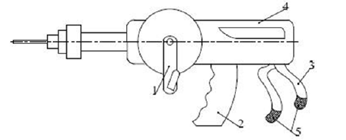
Figure 10: Hand-operated bone drills [22]. 1. Operating crank 2. Handle 3. Wrist strap 4. Assistant handle 5. Magic tape.
There is an assistant handle 4 at upper back end of the drill body. The appropriate handle shall be selected according to practical conditions. In practical application, operator holds handle 2 and wears the wrist strap 3 on the wrist. This enables operator to control drilling direction more easily and stably.
Current and future advancements
Feng [23] created a bone drill that could effectively prevent bone drillings splashing around during the drilling process. This reduces disturbances to the operator and protects patient’s safety. As shown in Figure 11, the drill bit 2 is mount on the spindle 4. Turn on the switch to start the bone drill. Spindle 4 will drive the drill bit 2 and drillings stirring gear 9 to rotate. The protective cover keeps bone drillings and flesh inside it. Accumulated bone drillings and flesh enter into the auxiliary protective containment 6 through the connecting pipe 8. Bone drillings will be sent to the catheter 10 by the rotation of drillings stirring gear 9. This could promise the smooth operation of surgery.
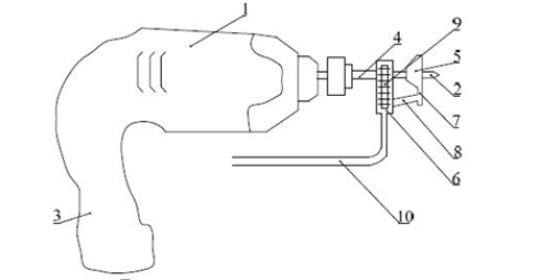
Figure 11: Bone drillings splashing preventive bone drill [23]. 1. The drill 2. Drill bit 3. Hand shank 4. Spindle 5. Protective cover 6. Auxiliary protective containment 7. Conduit ferrule 8. Connecting pipe 9. Drillings stirring gear 10. Catheter.
Xu et al. [24] developed a torque adjustable bone drill which is applicable to different positions of bones. As presented in Figure 12, the spring piece 11 contacts with the stop dog 10 continuously during the rotation of transmission shaft 6. The spring piece 11 will be bended and then passes through the stop dog 10. At this moment, the sum torsion generated by bending of spring piece 11 is the torque outputted by the transmission shaft 6. The torsion will bend the spring piece 11 which could be adjusted by the torque adjusting system. Therefore, fixed torque can be modified, and torque can be rotated with the same bone drill, saving purchase cost.
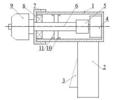
Figure 12: Torque adjustable bone drill [24]. 1. Shell 2. Hand shank 3. Switch 4. Motor 5. Spline housing 6. Transmission shaft 7. End cap 8. Bearing 9. Drill chuck 10. Stop dog 11. Spring piece
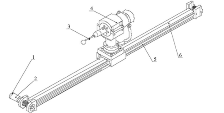
Louredo et al. [8] proposed a modern mechatronic bone drilling tool called DRIBON. The system relies solely on the measurement of the linear movement in order to control the drilling process as illustrated in Figure 13. The system includes a test bench, aims at driving drill bit to move along its axial direction to manage the rotation and linear movement of the drill bit. They put forward a mechanical design solution and its proper control algorithms, which have obtained improved results in terms of feasibility and detection time. DRIBON system can be combined with existing drilling tools without losing efficiency.
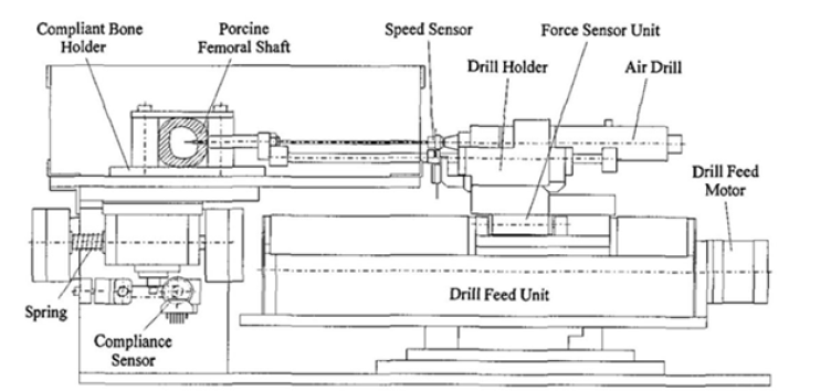
Another intelligent stand was proposed by Ong (1998) as presented in Figure 14, to identify the drill bit breakage during the drilling process. This system has additional sensors compared to the DRIBON, to record and monitor the good performance of the drilling process.
Knowledge-Based Transferable Oil Well Drilling Procedures and Frameworks
Highlighted below are possible transferrable knowledge and frameworks that could solve some of the key challenge problems associated to the need in meeting an precise competent operation of in-market bone drilling systems, upscaling the hands-on experience of the specialists performing the operation and improving the efficiency of bone canal drilling.
Modern drilling system for drilling through ice and gas hydrates systems
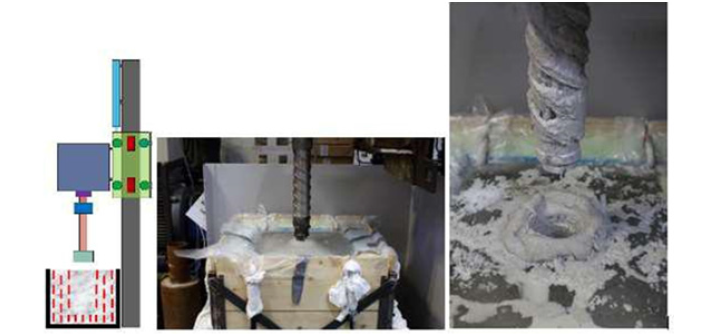
Teodoriu et. al [25] proposed a modern drilling system for drilling through ice and gas hydrates systems without melting the ice. His concept is called low energy high performance drill bit. The cutting-edge concept focuses on heat development during rock cutting process using a novel experimental setup capable to measure heat development during drilling in ice at a low-cost energy. The novel setup allows optimization of drilling bits and coring devices to work in low to medium consolidated formations. The setup was capable of running at constant WOB, ROP, flowrate which enhances the chances to drill in a gas hydrate like sediments while mitigating the heat development by controlling the drilling parameters. Figure 15 shows the schematic of the facility and a picture of the facility while testing the first ice sample. The lessons learned in this project can be adopted to bone drilling machine testing stand and bone drill parameters optimization with the effort of decreasing mechanical stresses that could lead to tissue damage. Furthermore, the geomechanics related knowledge will aid understanding the bone damage induced during high efficient drilling.
Drilling vibration setup
Laboratory scale experimentation has been a proven and convenient way of studying drilling processes and optimizing drilling efficiency. In their studies, Marquez & Teodoriu [26] and Srivastava & Teodoriu [27] proposed a modern drilling vibration setup (the longest stick-slip experimental setup worldwide) at the University of Oklahoma, USA. The amalgamated parameter model of this drilling vibration system provides an important understanding of vibration modes; axial (longitudinal) mode, torsional (rotational) mode, transverse (lateral) mode under variety of operating parameters and their influence on drilling performance and optimization. This setup is also dedicated to meet and exceed the training requirement of drilling operators, increasing efficiency and drilling performance in the oil and gas industry us to drill a high quality well at less cost per foot in the lowest time possible while also improving learning ability of young engineers at the university level. Figure 16 shows state of the art layout of the drilling vibration setup that can be modified to accommodate drilling through bones operations.
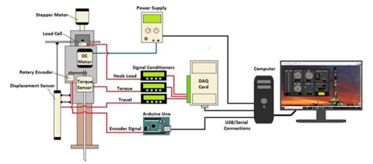
Figure 16: Schematic of a complex drilling setup showing the multitude of parameters to me collected and interpreted in real time, based on the actual drilling simulator at the University of Oklahoma.
Tapping into knowledge and previous experience in assessing the required parameters to understand how to optimize and eventually maximize the speed drilling can be put together in constructing bone drilling setup. This simulator will aid investigation of the effects of spindle rate, feed rate, depth of drilling and other related bone drilling procedures drawbacks during surgical operation in an effort to reduce causalities like metal stress to the operator and pains to patients. Furthermore, having a simplified and smart efficient bone drilling setup will allow monitoring of forces and temperature during drilling process. Additionally, the drilling shaft that connects the bit/mill to the drilling machine will be connected to sensors that can monitor the dynamic parameters such as RPM or torque. Our review shown in this paper have revealed that none of the equipment found in the literature is using high frequency sensors to measure and monitor not only the drilling parameters but also the vibrations induced during the drilling process.
Drill bit specifications, design and optimization
The drill bit plays a vital role, been the most essential tool in drilling operation. They differ based on shape, purpose and materials. The choice of the drilling bit and performance depends on several factors such as the oil formation to be drilled (soft, medium hard, medium soft or hard formation), cost of the bit, condition of the drilling bit, the weight applied to and the rate at which it is rotated. However, it is very important to keep written records of the drilling performance. Bits are worn by abrasion and shocks while drilling. The wear pattern is crucial, it should be inspected once the bit has been pulled and its grading should be recorded. Such records reveal the working life of the bit and aid the selection of the type of bit which may provide most efficient in a particular formation.
Several investigators conducted research related to drill bit selection and optimization that provides the maximum achievable ROP, suggested multiple approaches with machine algorithms to improve the reliability of oil well drilling bit design optimization process by ensuring that the expected directional behaviour of the drill bit is robust over a well-defined range of drilling parameters [28-33].
Literature shows that drilling parameters (drilling speed, feed rate, drilling energy, drilling depth) and drill specification (drill bit diameter, cutting fac, drill point, drill wear) are key parameters that influence orthopedic drilling during surgical process [2,34]. Several researches showed that many features of drill are responsible for increase in thermal injury to the bone and surrounding tissues.
Leveraging the knowledge and applied learnings from oil well drilling operation as related to drill bit optimization and performance could result in an improvement of drill design, drilling performance of the drill bit and its reliability and thus, refine the bone drilling parameters as subjected to bones and surrounding tissues. Continuous efforts by investigating and evaluate the several significant factors influencing the bone drilling on which no general agreement is yet been made will add enhance surgical operation. Better understanding of these factors will enhance the performance of the surgeon and the post-operative outcome for the patient.
Drilling operation training program
To work on an oil rig both onshore and offshore drilling operations, a specialized training is required and oil specialists meeting certain minimum standards. Companies do organize or collaborate with institutions to give an in-depth training module for drilling operations personnel (novice and experienced drillers) for procedures and upscale their proficiency most especially when a new drilling equipment’s or system is introduced or upgrade into the market. Training is accomplished using a virtual simulator with simple and challenging exercises, teaching students the drilling process, and allowing different drilling scenarios. It can be used for research to identify the importance of drilling parameters for drilling efficiency.
A typical example is drilling simulator laboratory at the Oklahoma University, USA that gives the students an early exposure as related to drilling processes in form of preplanning, day to day and post analysis tool technical know-how under field condition. The simulator is built along with industry expertise in generating virtual environments in which to train their drilling operations personnel for procedures on rigs. A similar simulator could be build to train doctors for drilling through bones operations.
Having a standardized training center with embedded simulator that support training and testing of new bone drilling equipment will create unique immersive learning experiences that allow medical students to safely apply their academic knowledge to real life scenarios. Extended knowledge from drilling operation training program will also play excellent role in bone drill design and parameters analysis, understand fracture mechanics and cracking process, condition monitoring and process optimization while eliminating possible clinical malfunction incidents while keeping high safety standards.
Conclusion
In this review, an attempt has been made to systematically organize the research investigations conducted on bone drilling, especially with respect to drilling equipment. The following conclusions can be drawn from this study:
- This approach will have a transformative effect on personal health and wellbeing, lower the rate of medication errors and health economy transformation with higher precision in risk identification to reduce health cost for an individual n health care system and population health management.
- The technology adaptation of OU drilling simulator will make bone drilling process more efficient while reducing patient recovery time and Xray exposure. Furthermore, having a bone drilling setup can also be used to further develop new tools or methods thus improving bone rod insertion. This approach will be unique for the medical industry since it will allow an independent and realistic comparison of various tools while the final goal is to provide an interactive and robust solution for training future specialists in a way very close to reality.
Conflict of Interest
The authors affirm that they have no known contending financial interests or personal relationships that could have appeared to influence the work reported in this article.
Acknowledgements
The authors would like to thank the Mewbourne School of Petroleum and Geological Engineering for support provided in other projects that made this paper possible.
References
- Szczęsny G, Olszewski WL, Zagozda M, Rutkowska J, Czapnik Z, et al. (2011) Genetic Factors Responsible for Long Bone Fractures Non-Union. Archives of Orthopedic and Trauma Surgery 131(2): 275-281.
- Pandey RK, and Panda SS (2013) Drilling of Bone: A Comprehensive Review. Journal of Clinical Orthopedics and Trauma 4(1): 15-30.
- Sui J, Sugita N (2019) Experimental Study of Thrust Force and Torque for Drilling Cortical Bone. Annals of Biomedical Engineering 47: 802-812.
- Bertollo N, Walsh WR (2011) Drilling of Bone: Practicality, Limitations and Complications Associated with Surgical Drill-Bits, Biomechanics in Applications, Vaclav Klika, Intech Open.
- Lughmani W, Bouazza-Marouf K, Ashcroft I (2013) Finite Element Modeling and Experimentation of Bone Drilling Forces. Journal of Physics Conference Series 451.
- Mediouni M, Schlatterer DR, Khoury A, Von Bergen T, Shetty SH (2017) Optimal parameters to avoid thermal necrosis during bone drilling: A finite element analysis. J. Orthop. Res 35: 2386-2391.
- Karmani S, Lam F (2004) The design and function of surgical drills and k-wires. Curr Orthop 484: 490-518.
- Louredo M, Díaz I, Gil JJ (2012) DRIBON: A mechatronic bone drilling tool. Mechatronics 22(8): 1060-1066.
- Vashishth D, Tanner, KE, Bonfield W (2003) Experimental Validation of a Microcracking-based Toughening Mechanism for Cortical Bone. J Biomech 36(1):121-124.
- Mediouni M, Schlatterer DR, Khoury A, Von Bergen T, Shetty SH (2017) Optimal parameters to avoid thermal necrosis during bone drilling: A finite element analysis. J. Orthop. Res 35: 2386-2391.
- Zhan XQ, Chen ZJ, Liu X (2010) Novel Cranial Drill.
- Jin CF (2010) Handle Automatic Burr Hole Instrument.
- Hao HN, Fu Y (2013) Novel directional electric bone drill.
- Liu ZH (2013) One Kind of Skull Drill.
- Min Yang, Changhe Li, Benkai Li, Yaogang Wan, d Yali Hou, et al. (2015) Advances and Patents about Medical Surgical Operation Bone Drilling Equipment. Recent Patents on Mechanical Engineering 8(2): 99-111.
- Yong DX, Jun Q, Zhenyu L, Yu YD, Zhang Y (2009) Intelligent Bone Drill and Control Method Thereof.
- Li CH, Ma HL (2013) Axial-Force-Controllable Surgical Bone Drill using Brazed PCBN (Polycrystalline Cubic Boron Nitride) Superhard Material Drill Bit. CN103070713.
- Li CH, Ma HL (2014) Axial-Force-Controllable Surgical Bone Drill using Brazed Twist Drill Bit.
- Li CH, Ma HL (2014) Axial Force Controllable Surgical Bone Drill with Abrasive Grain Bit.
- Fu HR, Liu HL, Zhang YR (2012) Automated Skull Drilling Mechanism.
- Li CH, Ma HL, Zhangdong K, Hou YL (2015) Ladder Drill Using Axial Force Controlled Surgical Bone Drill.
- Wang J, (2009) Hand-operated bone drill.
- Feng J (2015) A Bone-Bone Drill Cuttings Splash.
- Xu B, Li YQ 2(014) A Torque Adjustable Bone Drill.
- Teodoriu, C, Peitz R, Phochkhua G (2014) Experimental Study of Drilling through Gas Hydrates using a Novel Experimental Drilling Setup, DGMK Spring Conference (Frühjahrstagung), Celle, 24./25.
- Marquez A, Teodoriu C (2017) A Novel Drillstring Dynamics Experimental Setup to Be Integrated into Hardware in the Loop Capable Drilling Simulators. In: ASME. International Conference on Offshore Mechanics and Arctic Engineering, Polar and Arctic Sciences and Technology; Petroleum Technology. 8.
- Srivastava S, Teodoriu C (2019) An Extensive Review of Laboratory Scaled Experimental Setups for Studying Drill String Vibrations and the Way Forward. Journal of Petroleum Science and Engineering. 182.
- Pelfrene G, Al-Ajmi H, Bashir J, Al-Otaibi F, Al-Nuaimi A, et al. (2019) Statistical Optimization of PDC Bit Designs Based on 3D Simulations Applied to Demanding Directional Applications. Society of Petroleum Engineers.
- Abbas AK, Assi AH, Abbas H, Almubarak H, Al Saba M (2019) Drill Bit Selection Optimization Based on Rate of Penetration: Application of Artificial Neural Networks and Genetic Algorithms. Society of Petroleum Engineers.
- Bone K, Bradley B, Kale I (2019) Next-Generation Hybrid Drill Bit Produces Exceptional Drilling Dynamics and Time-Saving Improvements. Offshore Technology Conference.
- Bilgesu H, AL-Rashidi A, Aminian K, Ameri S (2000) A New Approach for Drill Bit Selection. Presented at the SPE Eastern Regional Meeting.
- Edalatkhah S, Rasoul R, Hashemi A (2010) Bit Selection Optimization Using Artificial Intelligence Systems. Petroleum Science and Technology 28(18): 1946-1956.
- Uboldi V, Civolani L, Zausa F (1999) Rock Strength Measurements on Cuttings as Input Data for Optimizing Drill Bit Selection. Presented at the SPE Annual Technical Conference and Exhibition.
- Vaughan RC, Peyton FA (1951) The influence of rotational speed on temperature rise during cavity preparation. J Dent Res 30(5): 737-744.



 We use cookies to ensure you get the best experience on our website.